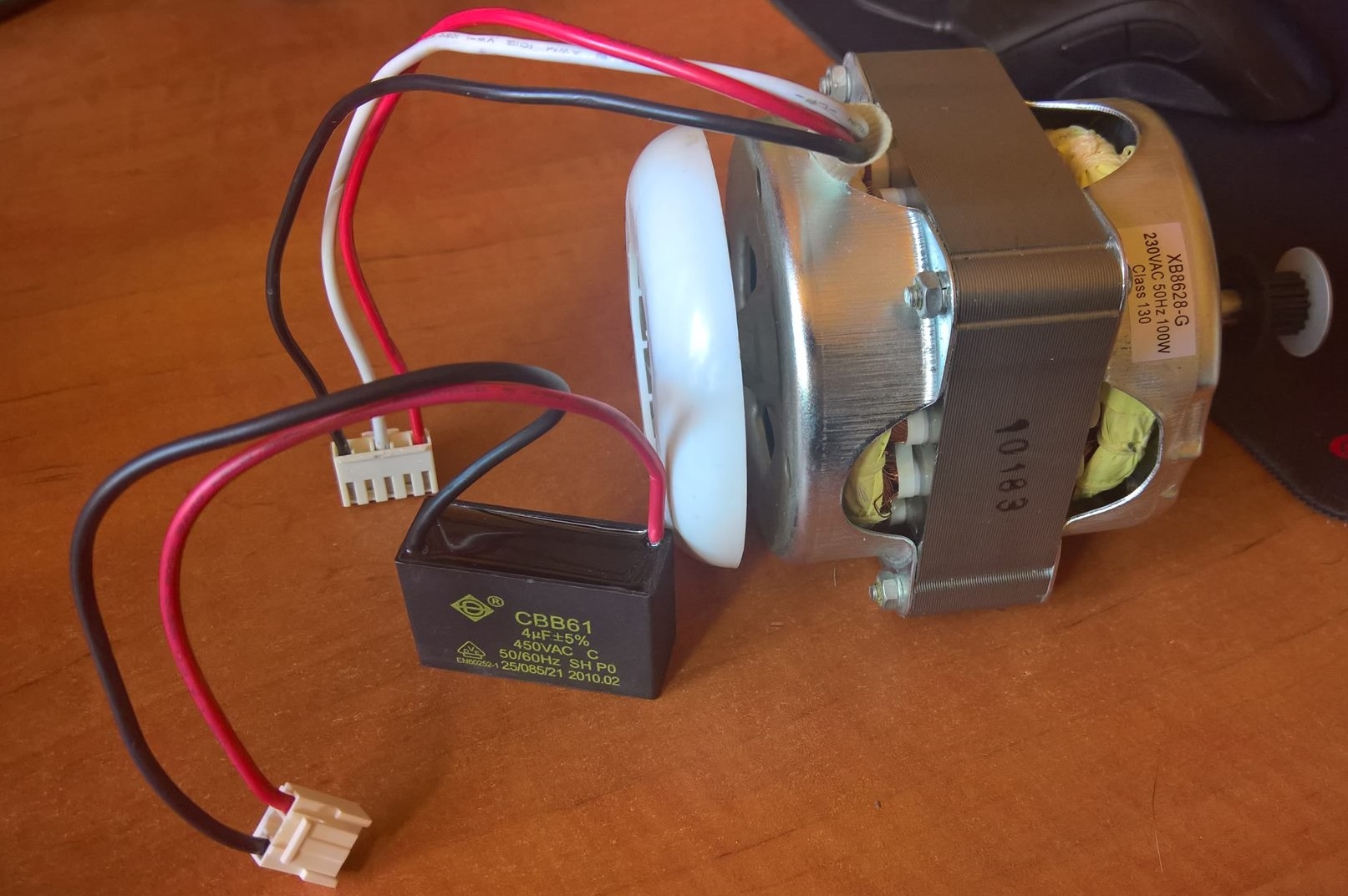
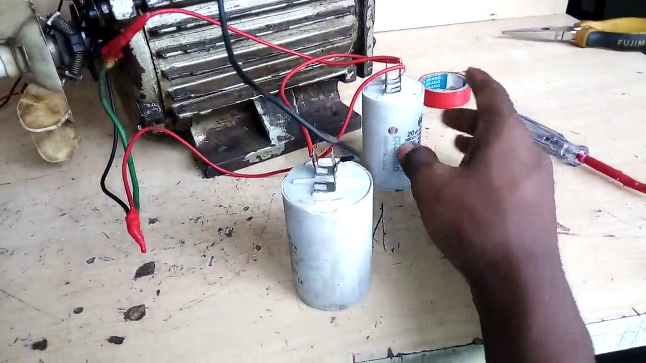
Singlephase motor 100 W 3 wires how to connect a capacitor and to the network
Components used to make the Single Phase Motor Capacitor Connection: 01. DP MCB: DP MCB In Two Pole MCB, switching & protection is affected in phases and the neutral. A Double Pole or DP Switch is a Switch that Controls two Circuits at the same time. In terms of Residential Switching, this Normally means it Switches the live and Neutral at the.
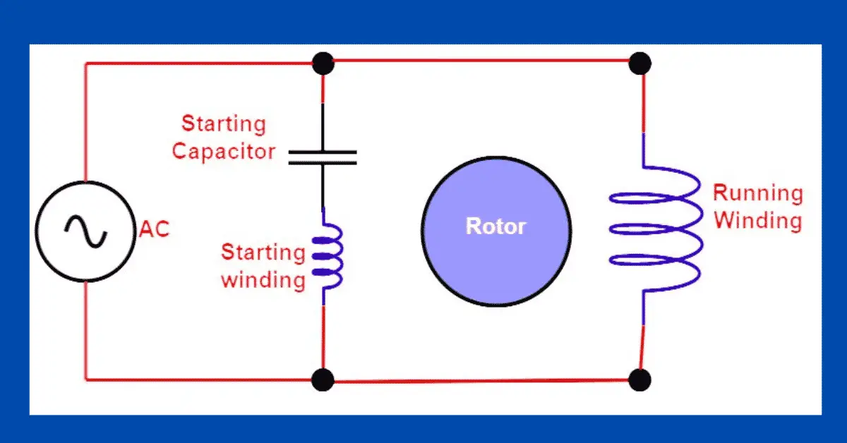
Single Phase Motor Winding Connection With Capacitor
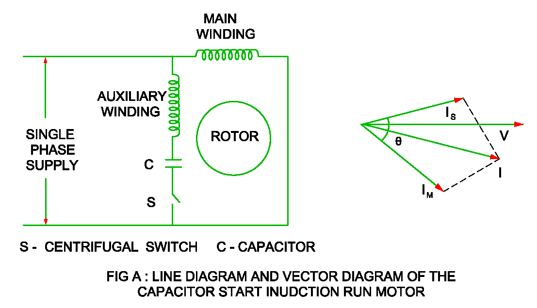
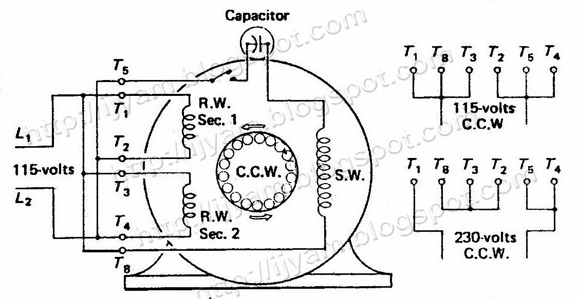
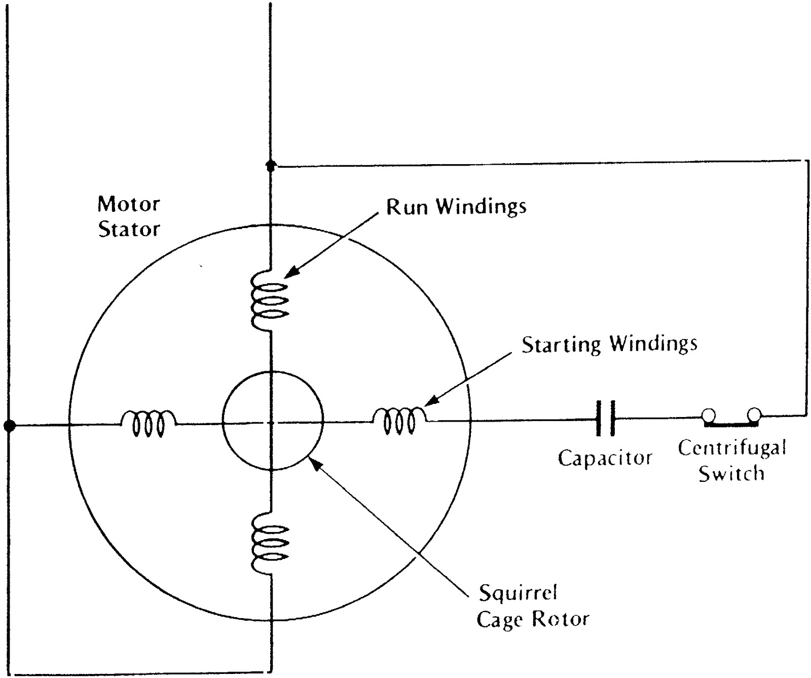
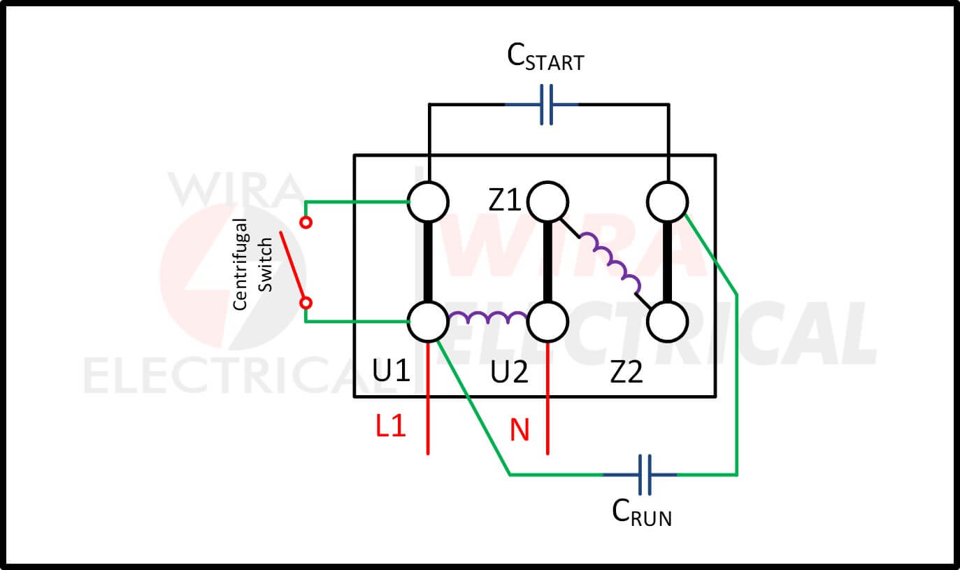
In this post, I share a One-phase motor capacitor start and capacitor Run wiring connection diagram. In the above single-phase motor capacitor and capacitor run diagram, I have shown the motor auxiliary and main winding. I have shown the starting capacitor with the centrifugal switch and the Running capacitor direct to the motor auxiliary winding.
Why capacitor is required for Single phase motor?
Below is the single phase motor centrifugal switch diagram. The centrifugal switch is used to connect the auxiliary winding with the capacitor and the power source. Once the speed reaches a certain value, the switch will disconnect the capacitor and the auxiliary winding from the power source.

How To Wire Single Phase Motor With Capacitor
What's one way to solve the single phase problem? Build a 2-phase motor, deriving 2-phase power from single phase. A three-phase motor may be run from a single-phase power source. However, it will not self-start. It may be hand started in either direction, coming up to speed in a few seconds.
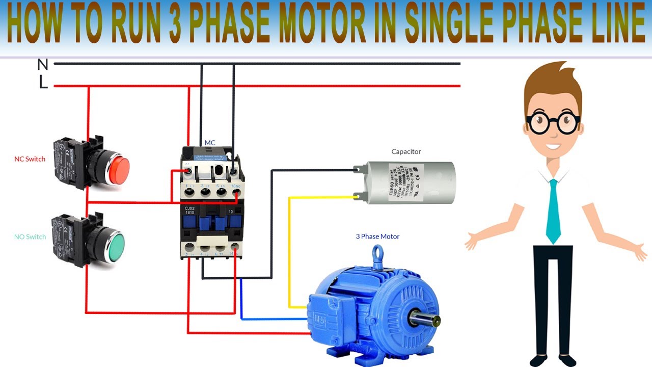
How to Run 3 Phase Motor in Single Phase Line Wiring capacitor for 3 phase motor with single
Single phase motor wiring diagram with capacitor start and capacitor run In This Video we will Learn how to connection of single phase motor with two Capacitors in very easy and.

Capacitor Single Phase Motor Wiring Diagram Wiring Diagram Schematic
Step One - First, perform a simple visual inspection of the capacitors. Check for any leakage, cracks, or bulges, and see if the membrane on the top of the capacitor is still in place. Step Two - If there are no visual indicators of failure, you'll need to test the capacitance of the capacitor with a multimeter.

How To Connect Capacitor With Single Phase Motor
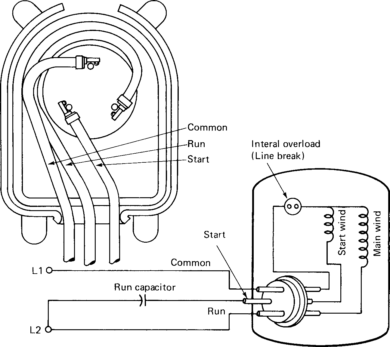
1 All the information is there. The wiring colours to the motor suggest that this is a three phase motor, just to confuse me. However yellow is the start switch blue is the auxiliary winding and red is the main winding. Run capacitor at the top, start capacitor at the bottom. This gives the following circuit diagram.

Single Phase Motor Connection with Two Capacitors chakki motor connection diagram YouTube
How to Connect a Single Phase Motor Jean B 22.6K subscribers Subscribe Subscribed 563K views 4 years ago This video will show you how to connect a Single phase motor with two capacitors. A.
[DIAGRAM] 220 Volt Single Phase Capacitor Start Motor Wiring Diagram
Single phase motor Connection with two capacitor How to Wire a Motor Capacitor? Instructions: Here are some additional tips for How to Connect a Capacitor to a Single-Phase Motor: How AC Single-Phase Induction Motors Work? Why Capacitor is Required for Single Phase Motor? The Importance of Capacitors in Single-Phase Motors Types of Capacitors 1.

230v Single Phase Capacitor Wiring Diagram Diagrams Schematics For Fancy Motor Run 11
Limitations of Single Phase Motors. Even with the additional auxiliary winding, a single-phase induction motor suffers from several limitations compared to a three-phase motor. The phase shift provided by a run capacitor changes with the motor's speed, which means efficiency is not consistent as the motor changes speed.
Single Phase Motor Wiring Diagram With Capacitor Wiring Diagram
capacitor start & run motor connection. how to connect single phase motor
Single Phase Motor Wiring Diagram With Capacitor Wiring Diagram
To select the correct capacitance value, start with 30 to 50μF/kW and adjust the value as required, while measuring motor performance. We also can use this basic formula to calculate capacitor sizing : 2) Determine the voltage rating for capacitor. When we select the voltage rated for capacitor,we must know the value of our power supply.For.
Single Phase Motor Capacitor Wiring Diagram
How to connect a single phase motor and identify each winding lead ? - YouTube 0:00 / 2:25 Intro How to connect a single phase motor and identify each winding lead ? Electrical Engineering.
Single Phase Motor Wiring Diagram and Examples Wira Electrical
A 2-phase motor is an electrically-powered rotary machine that can turn electric energy lines into mechanical energy. It works by using a single-phase power supply 220V ac line. They.

What Size Capacitor Do I Need For A Single Phase Motor
Example1: Calculate the rated required capacitance value for the single-phase, 220V, 1 HP, 50Hz, 80% of the motor. 1 HP = 746 Watts. Use our capacitance calculation formula. C (µF) = 746 x 80 x 1000 / (220 x 220 x 50) = 24.66 µF. Hence 1 HP Motor required 24.66 µF capacitance to start the motor smoothly. But in the market, you can get 25 µF.

Single Phase Capacitor Start Motor Wiring Diagram Database
Step 1 Use a screwdriver to remove the screws holding the terminal connector panel on the AC single-phase motor. Remove the panel using your fingers. There are three connectors: live, neutral and ground. Loosen the three terminal screws using a screwdriver, but don't completely remove the screws. Step 2
