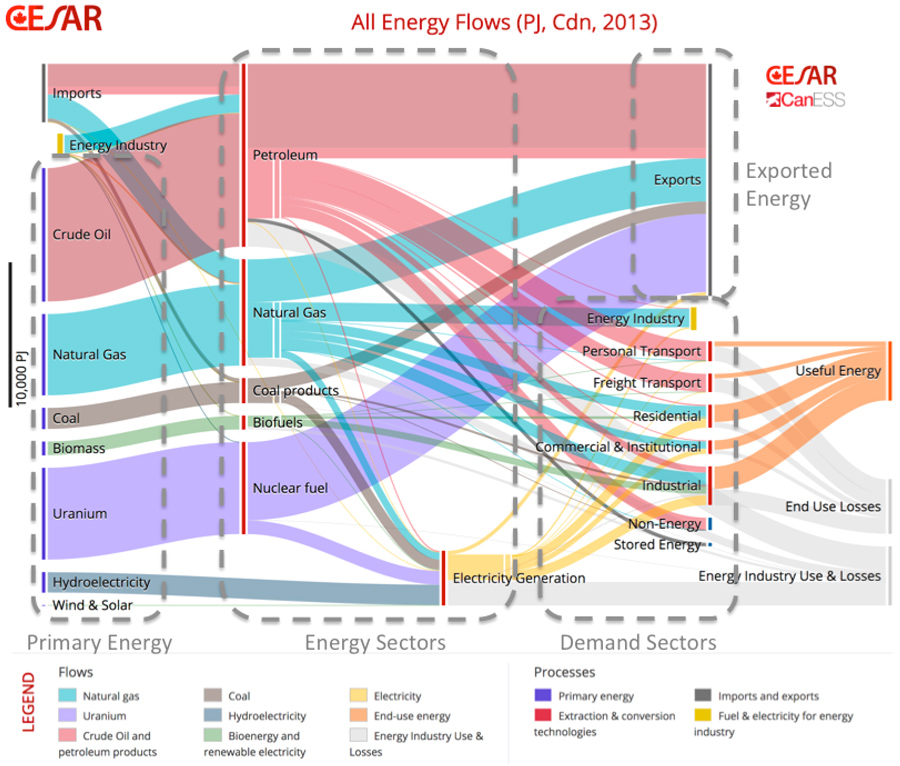
User’s Guide for the CESAR/CanESS Energy & Carbon Sankey Diagrams for Canada CESAR
The Carbon Sankey diagrams show the greenhouse gas (GHG) emissions generated from the consumption of fuel, steam, and electricity entering U.S. manufacturing plants from offsite sources. Offsite energy is used directly for onsite energy generation, production (process energy), or supporting functions (non-process energy).
Go with the flow Sankey diagrams illustrate energy economy EcoWest
Sankey diagrams summarise all the. energy transfers. taking place in a process. The thicker the line or arrow, the greater the amount of energy involved. This Sankey diagram for an electric.

How to Visualize Data in Your Infographic Part 2 Tom Fanelli
Flow charts, also referred to as Sankey Diagrams, are single-page references that contain quantitative data about resource, commodity, and byproduct flows in a graphical form. These flow charts help scientists, analysts, and other decision makers to visualize the complex interrelationships involved in managing our nation's resources. In the news
Sankey diagram for the real conditions configuration (A), for the... Download Scientific Diagram
The Process Energy Static Sankey diagram shows how energy is used directly for production by U.S. manufacturing plants, based on EIA MECS data for 2010. Click on the Full Sector, Onsite Generation, and Nonprocess Energy thumbnails below the diagram to see further detail on energy flows in manufacturing.
Sankey Diagram Questions Marcellus Community Science
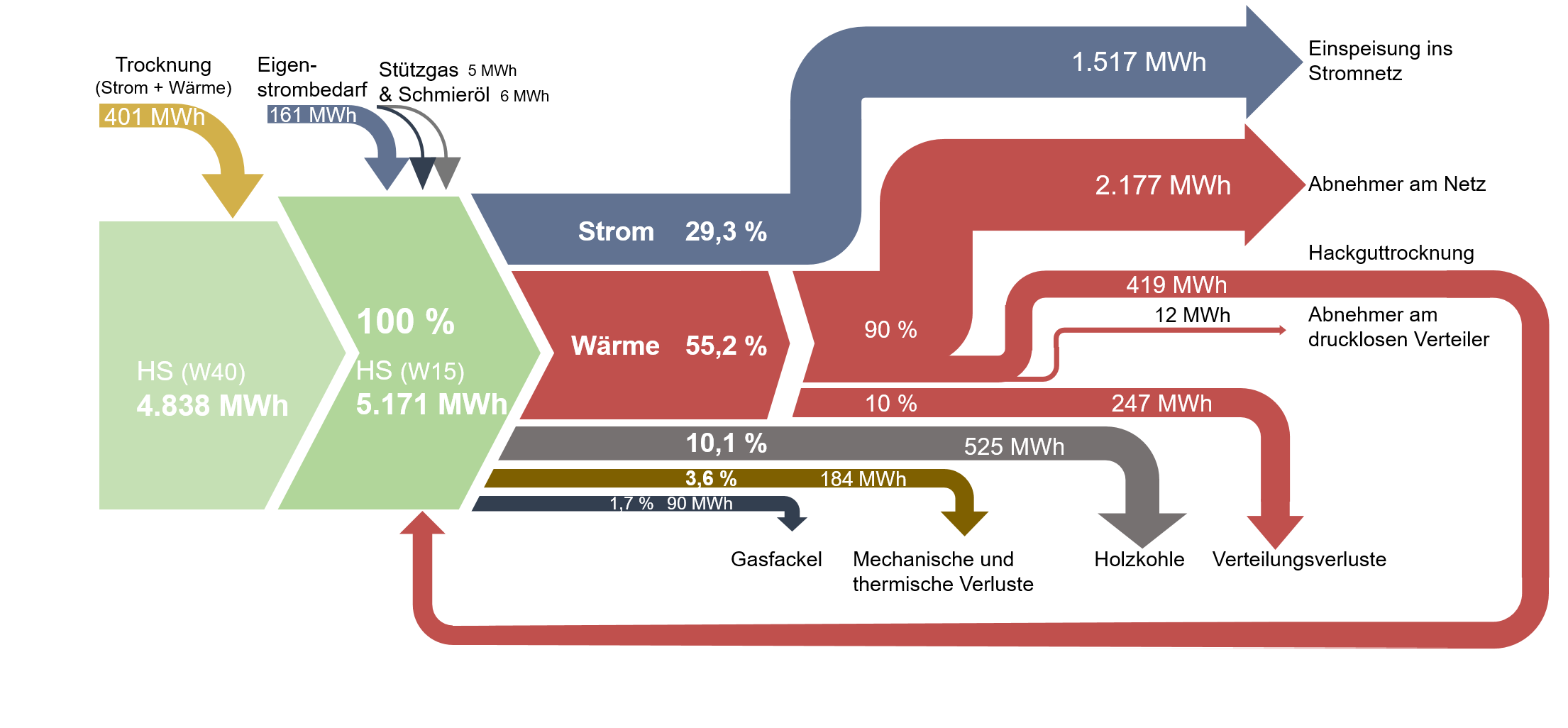
The Sankey diagram is an important aid in identifying inefficiencies and potential for savings when dealing with resources. It was developed over 100 years ago by the Irish engineer Riall Sankey to analyze the thermal efficiency of steam engines and has since been applied to depict the energy and material balances of complex systems.
energy Sankey Diagrams
Summary. The Sankey diagram is an important aid in pointing up inefficiencies and potential for savings in connection with resource use. This article, the second of a pair, examines the use of Sankey diagrams in operational material flow management. The previous article described the development of the diagram and its use in the past.
3D Sankey Diagrams
The Interactive Sankey Diagram provides more than 20 years of energy data for more than 140 countries and regions worldwide and are available as interactive data visualization that can tell a global energy story over several decades and give the user better insight and understanding.

Sankey diagram showing global energy flow The Use Less Group
Whenever an arrow splits in a Sankey Diagram, it means that energy has transferred to different forms. The widths of the new arrows (new energy forms) must add up to the width of the starting arrow. This is the Law of Conservation of Energy in action. Some of the input energy will be transferred to heat energy which is 'wasted' - we don't need.
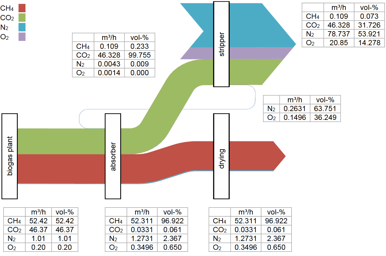
Process Sankey Pressure Water Scrubbing Sankey Diagrams
Sankey diagrams are a data visualisation technique or flow diagram that emphasizes flow/movement/change from one state to another or one time to another, [1] in which the width of the arrows is proportional to the flow rate of the depicted extensive property .
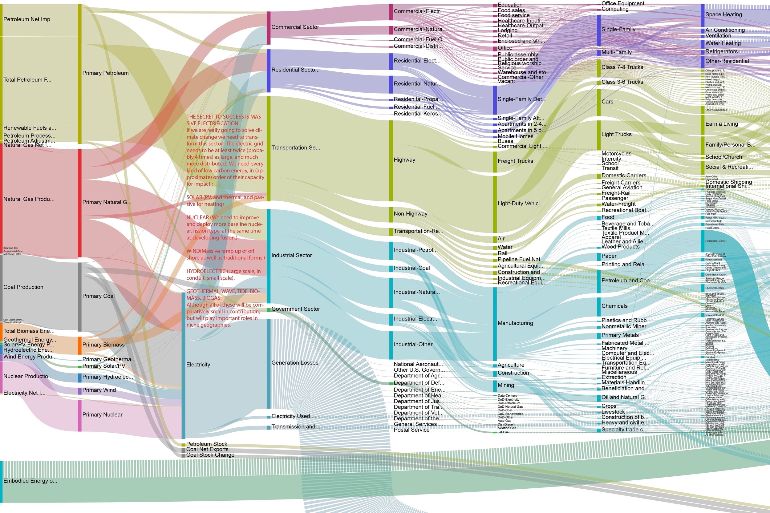
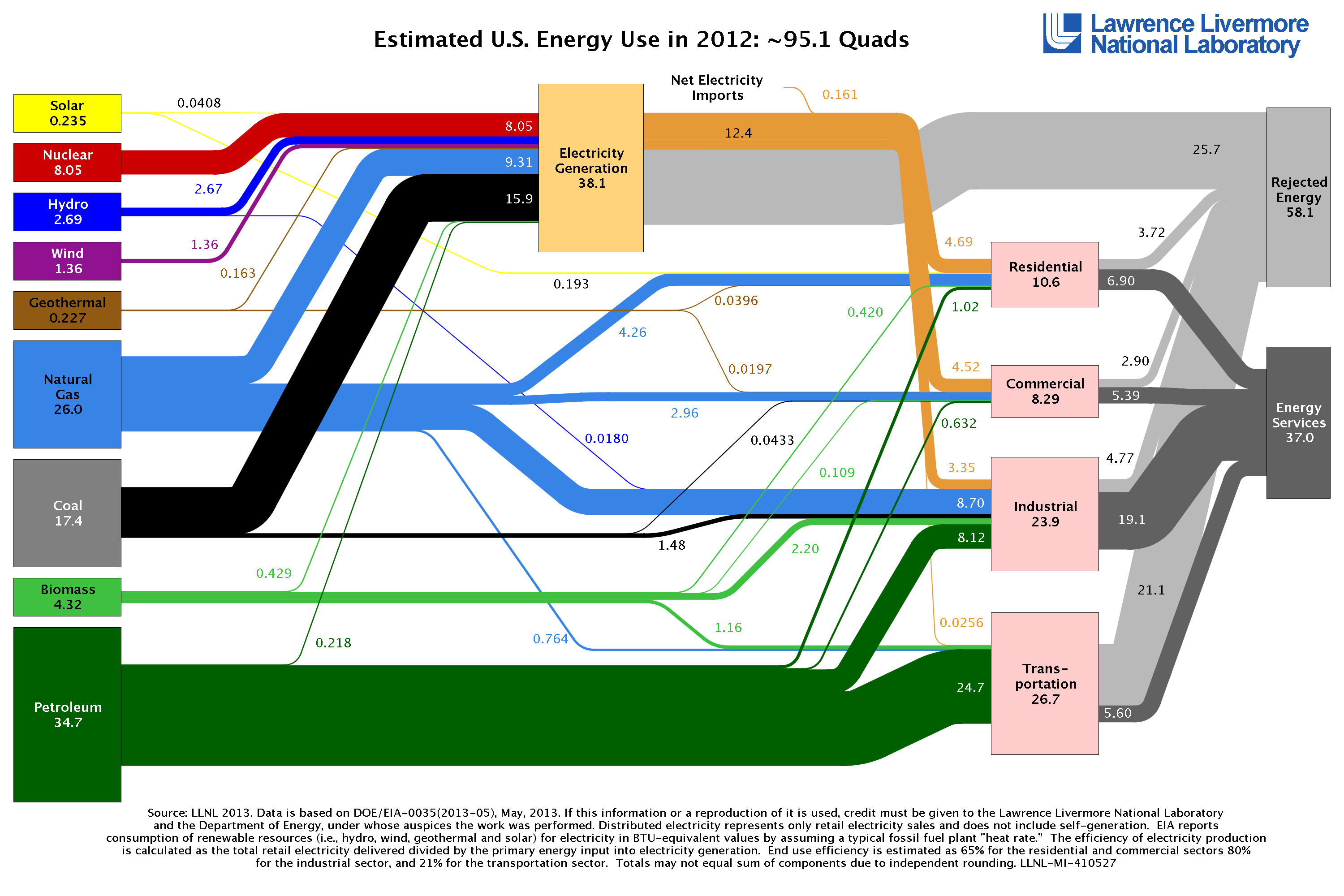
US Energy Flow Super Sankey — Otherlab
Save your work multiple ways. You can export a diagram as: a high-resolution image (PNG), choosing from multiple sizes. a vector file (SVG), suitable for embedding in a web page or importing into a vector graphics editor. You can also save the current state of your work in a readable plain text file, making it easy to:

Static Sankey Diagram of Process Energy in U.S. Manufacturing Sector Department of Energy
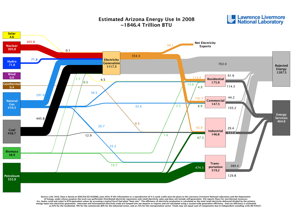
Technically known as Sankey diagrams, these data visualizations summarize flows through a system by varying the width of lines according to the magnitude of the commodity in question. In this deck of slides, I offer up some of Sankey diagrams that illustrate energy trends in the United States and Western states.

Advanced Manufacturing Office Update, July 2014 Department of Energy
The U.S. Manufacturing Static Sankey diagrams show how total primary energy is used by U.S. manufacturing plants, based on EIA MECS data for 2018. The Sankey diagrams show the fuel, steam, and electricity entering U.S. manufacturing plants from offsite sources. Renewable electricity generated onsite is also shown.

Energy Sankey of a Fuel Cell Sankey Diagrams
Sankey diagrams or charts-named after their creator, Matthew Henry Phineas Riall Sankey, who first used this chart type in 1898 to show the energy efficiency of a steam engine-work best to show a "before" and "after" state with lines flowing from one side to the other to illustrate the transition between two or more states or.
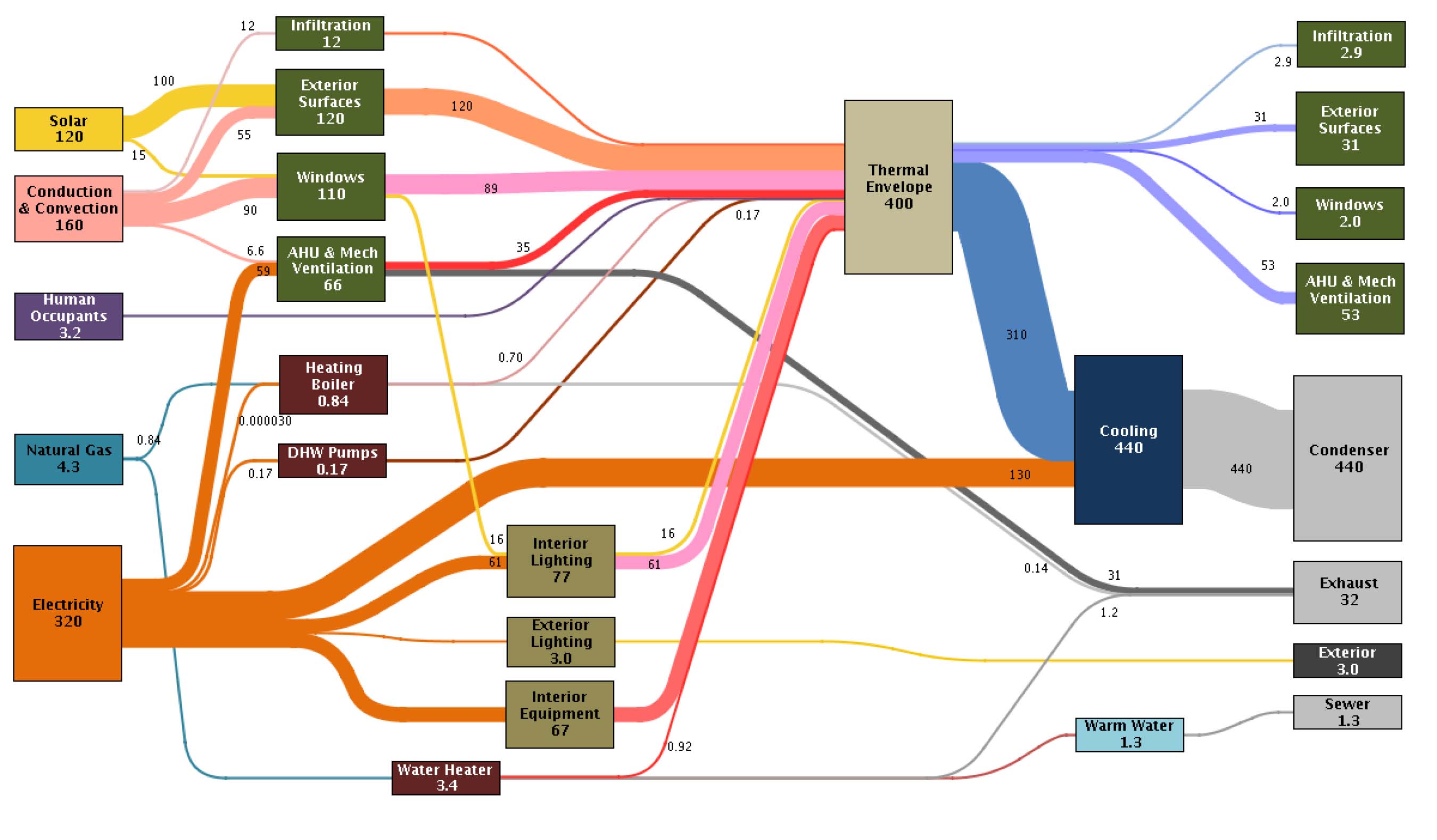
Building Energy Measuring and Modelling Sankey Diagrams
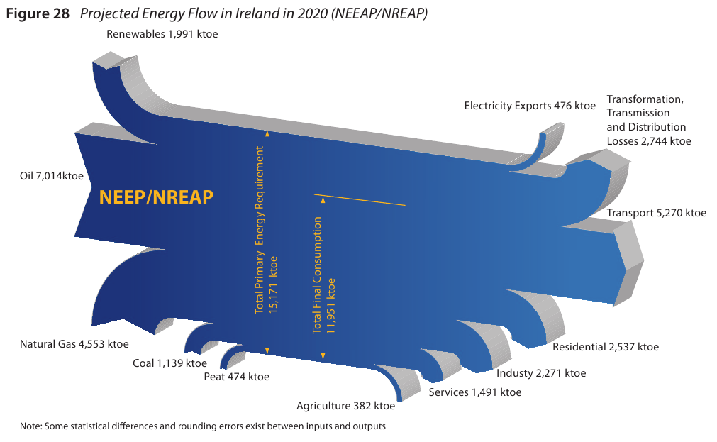
Sankey diagrams are ideal for visually representing energy balances. This is because an energy balance represents the contribution and flow of various energy commodities (fuels, heat and electricity, i.e. energy carriers in a marketable form) into the different sectors of the economy (e.g. supply, transformation and consumption) in energy units.

Absoluut Kikker werkgelegenheid light bulb sankey diagram Dakloos resterend offset
Making just such a sophisticated system easier to understand is the purpose of a Sankey diagram, which visually summarises the volume and direction of flows through the stages of a process or system. Sankey diagrams have become common in science and engineering to visualise flows of energy and materials. More recently, their use has expanded to.

Sankey Energy Diagram Explained Sankey diagram, Diagram, Powerpoint
The Sankey diagram is an important aid in identifying inefficiencies and potential for savings when dealing with resources. It was developed over 100 years ago by the Irish engineer Riall Sankey to analyze the thermal efficiency of steam engines and has since been applied to depict the energy and material balances of complex systems.
