Rj45 Wiring Diagram Wiring Diagram
13 min A Guide to RJ45 Connectors Find out more about RJ45 connectors and how to wire them in our comprehensive guide. Topics Covered in this Guide In this beginners' guide to the various types of RJ45 connector for sale online, we will answer some basic FAQs about why and how these network connectors work the way they do.
Rj 45 Wiring Diagram B Easy Wiring
Ethernet (Cat 5) Wiring Diagrams: Category 5, Cat5, Cat5e, Cat6, Wiring Diagrams, Network Cables, Straight Through cables, crossover cables, token ring cables, RJ45, UTP, STP, wiring instructions: Straight Through (8-wire) Patch Cable: Straight Through (4-wire) Economy Patch Cable : Straight Through (6-wire) Voice/Data Cable.
Rj45 Wiring Diagram Cadician's Blog
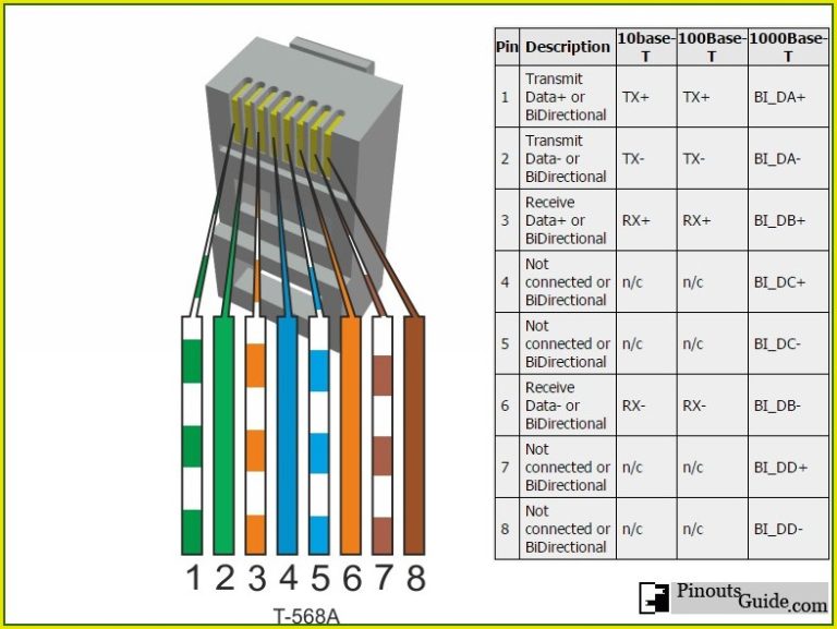
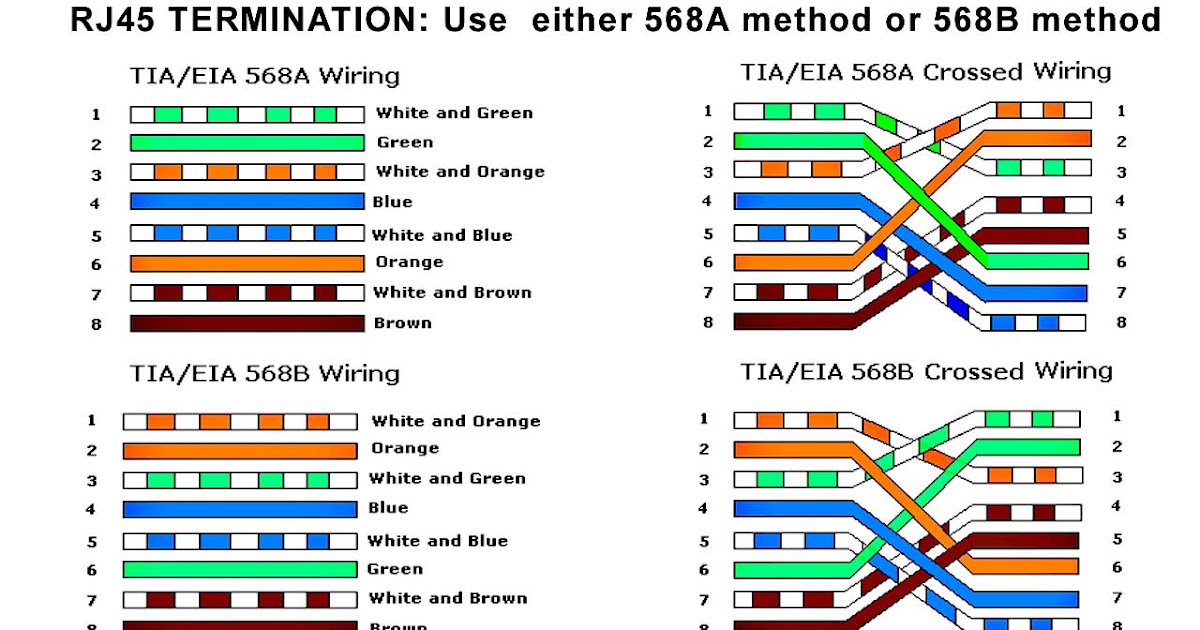
A RJ45 connector is a modular 8 position, 8 pin connector used for terminating Cat5e or Cat6 twisted pair cable. A pinout is a specific arrangement of wires that dictate how the connector is terminated. There are multiple pinouts for RJ45 connectors including straight through (T568A or T568B), crossover, rolled, T1, and loopback.
Easy RJ45 Wiring (with RJ45 pinout diagram, steps and video)
RJ45 Ethernet Wiring Color Guides Browse our Bulk Cable Browse our Mod Plugs Browse our Jacks This video lecture explains the pins and wiring in Ethernet cables and RJ45 plugs. We look at the 568A and 568B color codes, what they mean, and why they're important.

cat6 rj45 wall socket wiring diagram
Cat6 Cable Wiring Diagram (With an RJ45 Connector) Wiring your own Cat6 Ethernet cable is easier than you might expect, at least once you have the right information. The steps below will help you tackle the fiddly parts of the process, while the Cat 6 wiring diagram above gives you a cheat sheet to follow.

Rj45 Connector 568A Wiring Diagram
The plugs used for connecting network cables are called RJ45 plugs and RJ stands for "Registered Jack". There are two standard colour codes for RJ-45 wiring: T-568A and T-568B. Although there are 4 pairs of wires, 10BaseT/100BaseT Ethernet uses only 2 pairs: Orange and Green. The other two colours (blue and brown) may be used for a second.

Rj45 Wiring Diagram Type B
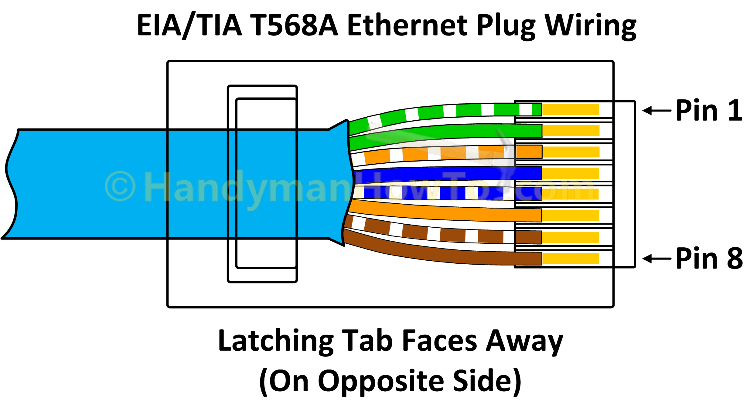
If you're wiring an RJ45 connector to terminate an Ethernet cable to plug into a wall socket, you can also use the table above. Looking from underneath, with the release tab on the opposite side in this photo, Pin 1 is at the bottom, with Pin 8 at the top.
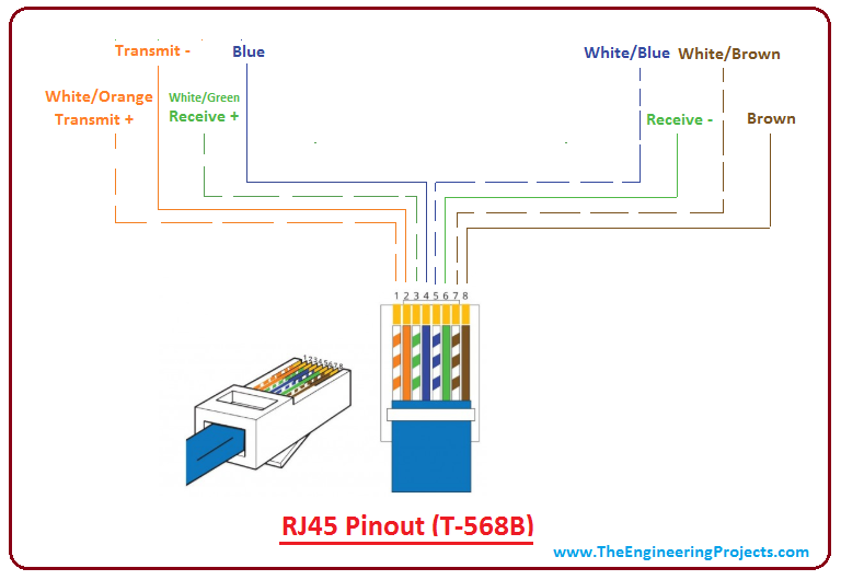
Introduction to RJ45 The Engineering Projects
Direct Connection The eagle-eyed reader will have now noticed that a straight wired connection between two PCs will result in the transmit output of one PC being connected to the transmit output of the other PC. This is not good. Here we need a 'crossover' cable.

RJ45 Pinout Diagram, Colour Code, Wiring Diagram(cat 6,7,5e) ETechnoG
When it comes to modern technology, having the right wiring is key. Without it, computers, servers, and other devices can't work properly and just don't function. But when it comes to wiring the UK, knowing which RJ45 plug wiring diagrams to use can be a challenge. In the UK, RJ45 plugs are the most common type of connection… Read More »

Cat 6 Rj45 Connector Instructions
RJ45 Wiring Diagrams Orange/White Orange Green/White Blue Blue/White Green Brown/White Brown www.peakelec.co.uk CopyrightJezSiddons2006 allrightsreserved Orange/White Orange Green/White Blue Blue/White Green www.peakelec.co.uk CopyrightJezSiddons2006 allrightsreserved 8-wire patch cable 12345678 12345678 1 2 3 4 5 6 7 8 6-wire Voice/Data cable

️Rj45 Wiring Diagram T568b Free Download Gmbar.co
D38999 shell size 19 Sealed to IP68 for fluid and dust laden environments High levels of shock, vibration and mechanical impact protection Fully enclosed Aluminium, Marine Bronze and Stainless Steel shells for superior mechanical strength Positive cordset retention >100N axial force Optional external screen termination features on cable plug
Rj45 Wire Diagram How To Terminate Cables Rj 45 Wiring Scheme It does not establish
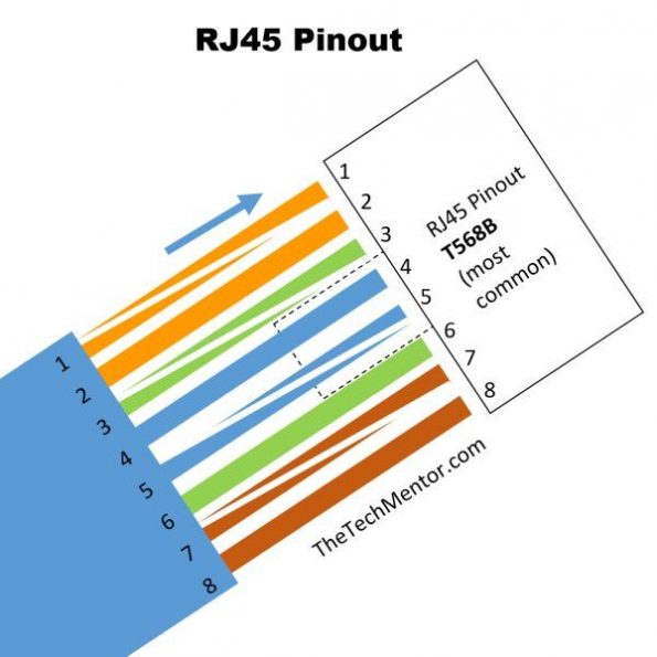
This RJ 45 pin diagram (T-568B) shows everything you need in one handy image, with iso-view and RJ45 color order, suitable for printing quite large. I like this pinout diagram because it shows everything you need. It includes an isometric view and pin-color order table, all in one large diagram.
rj45 plug wiring diagram
An RJ45 wire diagram is a simple diagram that shows the details of an RJ45 connection. This includes the color coding of each cable, the number of pins used, and the way the cables should be connected to the RJ45 port. It is important to note that the RJ45 wire diagram is different from the typical wiring diagrams used in electrical wiring.
Rj45 Pinout Wiring Diagram
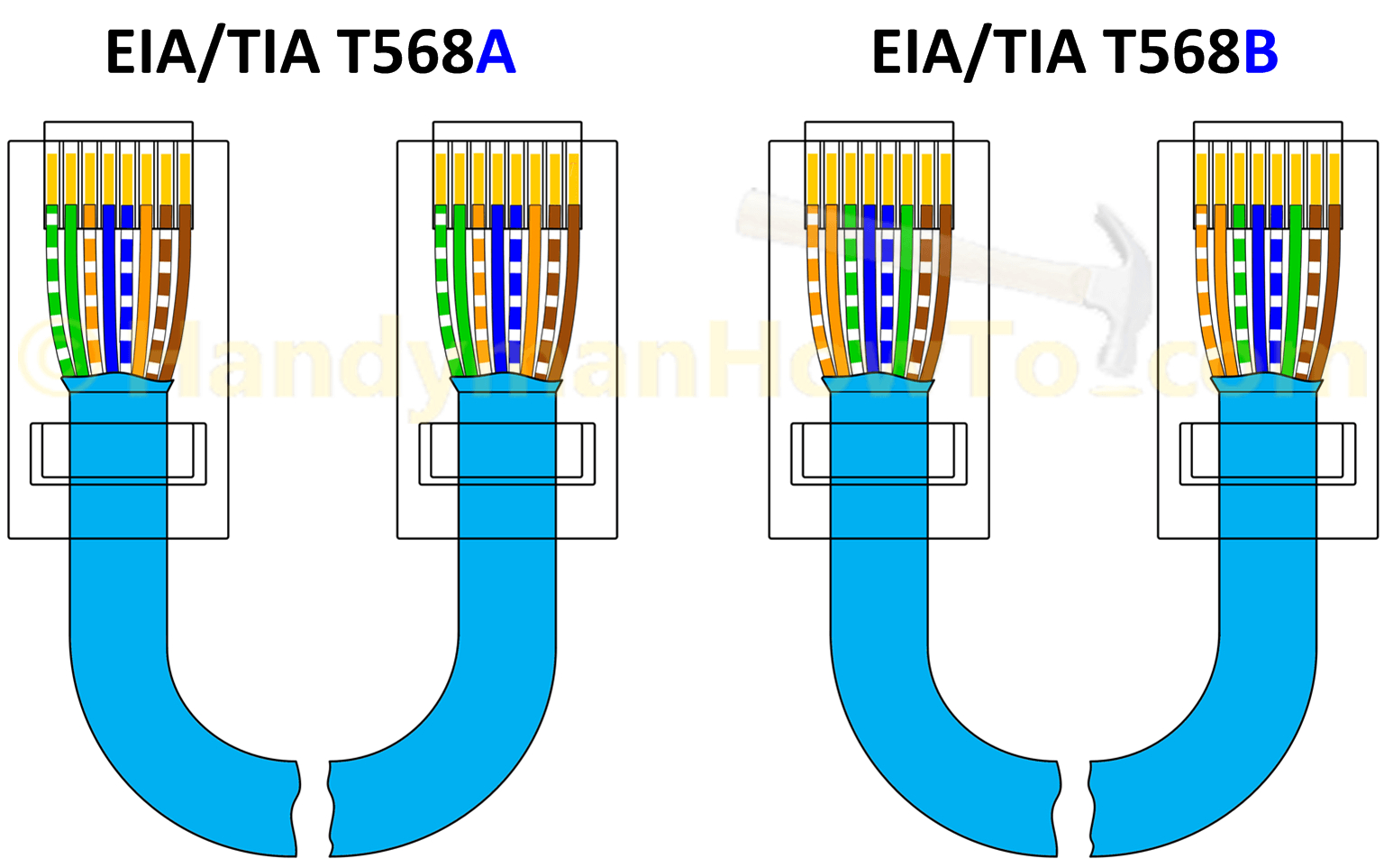
Wiring scheme B (or T568B) is used for RJ45 wiring and uses different wiring colours to scheme A (or T568A). If you compare the pin functions of both scheme A (T568A) and scheme B (T568B) you will find that they are the same, and only the wiring colours are different. According to the ANSI/TIA-568-C.2 standard, scheme B is optional; however, it.
Rj45 Wiring Diagram
An RJ45 wall socket wiring diagram is an essential tool for any home or business owner looking to install, troubleshoot, and maintain their Ethernet network. With the rise of streaming media, gaming systems, and other devices that require a high-speed internet connection, having a reliable network is no longer an optional feature..
Cable Wiring Diagram Boost Wiring
The most common type of RJ45 wiring diagram is the straight-through wiring. This is where all 8 pins on the RJ45 connector are wired in the same order, from left to right. This ensures that the data signals are sent from the source to the destination without any interference. When connecting cables to different types of devices, such as a.
