Best Of Wiring Diagram Micro Usb diagrams digramssample diagramimages wiringdiagramsample
Connecting the USB Type-C cable creates a current path from 5-V supply to ground. Since there's only one CC wire inside the USB Type-C cable, only one current path is formed. For example, in the upper graphic of Figure 4, the CC1 pin of the DFP is connected to the CC1 pin of the UFP. Hence, the DFP CC1 pin will have a voltage lower than 5 V.
USB Wiring Code Wiring Diagram
Everything You Need to Know About USB Cable Schematic DiagramsThe concept of electrical wiring diagrams has always been present in the world of electronics. From everyday electronic gadgets to complex industrial systems, these diagrams are essential for ensuring accurate connections and a properly functioning system. USB cables are no exception, and understanding their schematic diagrams is an.

RC USB over Cat6
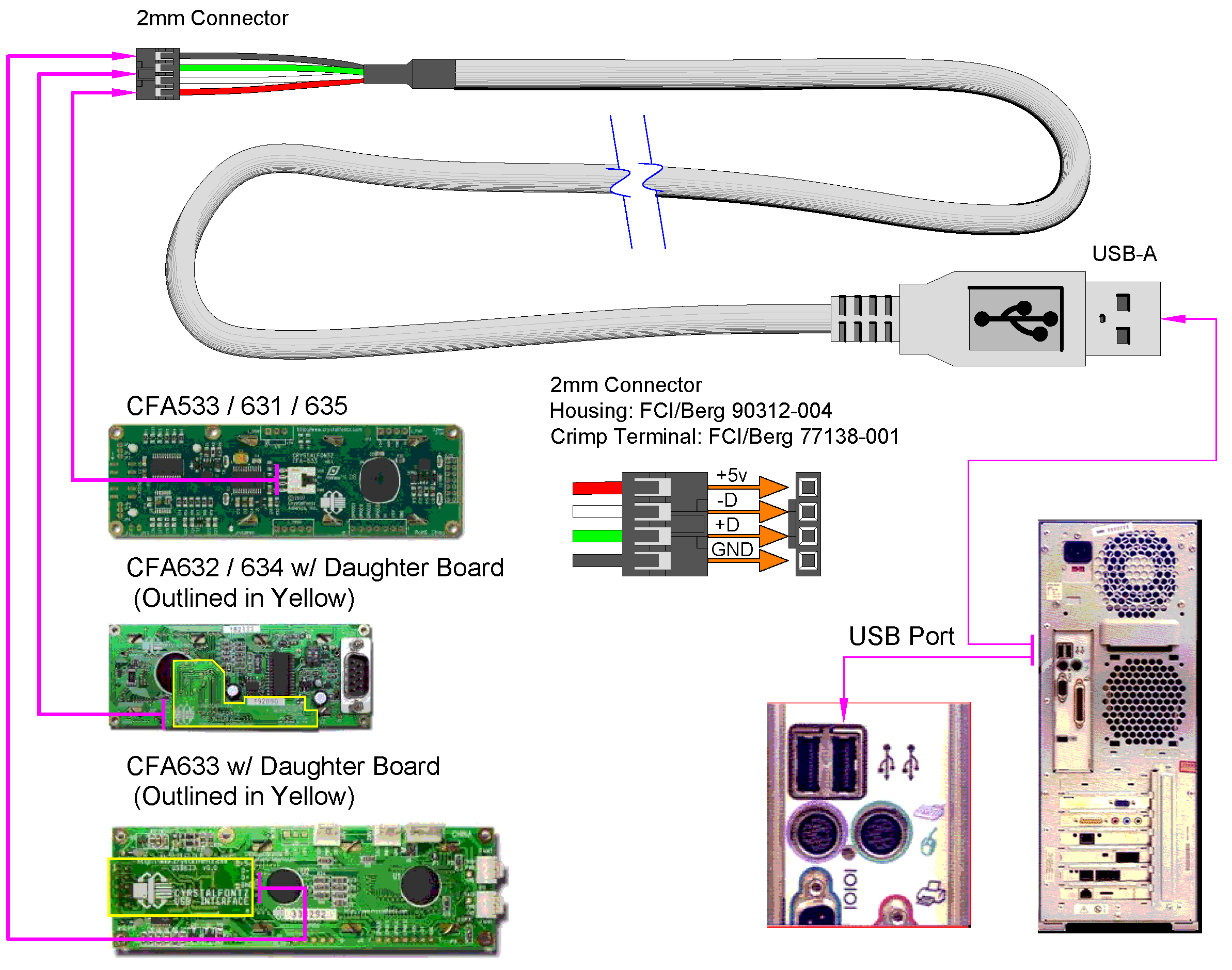
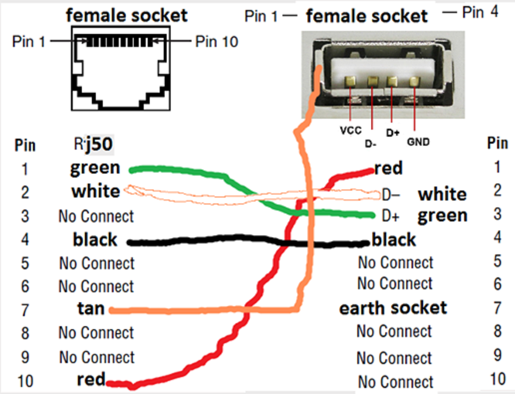
The schematic diagram also shows the wiring connections between the USB connectors and the corresponding pins or wires inside the cable. In addition to the standard USB cable schematic diagram, there may be variations for different types of USB cables, such as USB 3.0 or USB Type-C.

Micro Usb Cable Wiring Diagram Extension Different Wire Color Data Usb Cable Usb Cable
The USB Type C wiring diagram is a visual representation of how the different components of a USB Type C cable or connector are connected. It provides a clear understanding of the wiring and can be used as a reference when designing or troubleshooting USB Type C connections.

Usb To Mini Usb Wiring Diagram, Ide To Usb Wiring Schematic Wiring Diagram
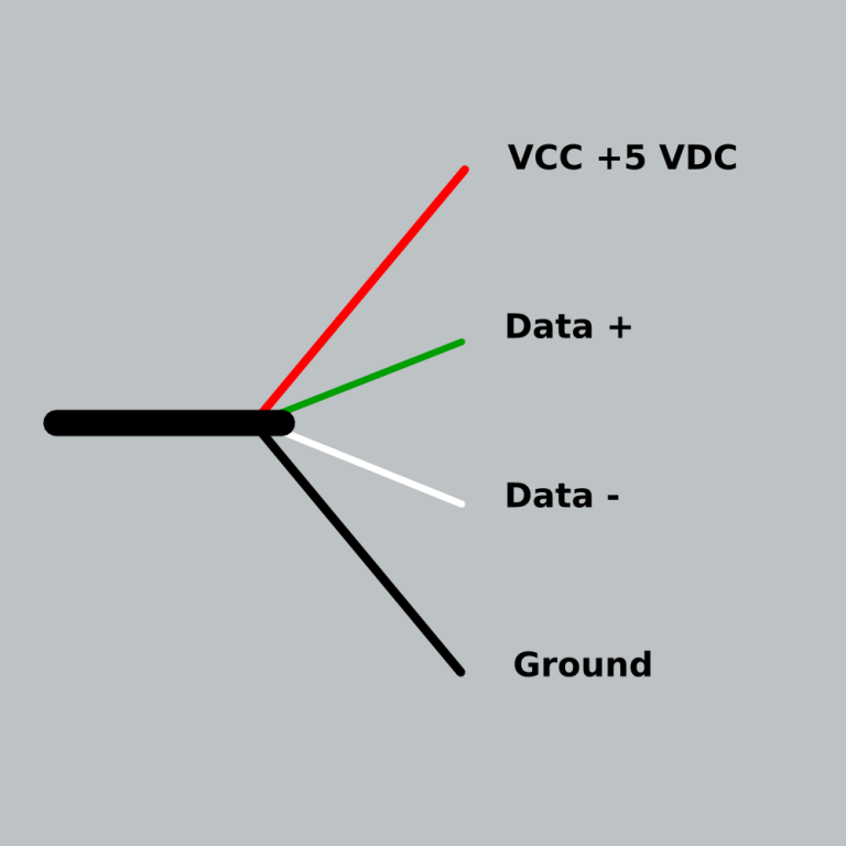
USB A, B 2.0 and 3.0 Cable Pinout. The USB cable provides four pathways- two power conductors and two twisted signal conductors. The USB device that uses full speed bandwidth devices must have a twisted pair D+ and D- conductors. The data is transferred through the D+ and D- connectors while Vbus and Gnd connectors provide power to the USB device.