a f sensor toyota wiring diagram
The 3 wire mass air flow sensor wiring diagram is a simple and effective way to properly wire a mass air flow (MAF) sensor. It is important to understand the wiring diagram when installing a mass air flow sensor in a car, as it will ensure that the sensor is correctly wired.

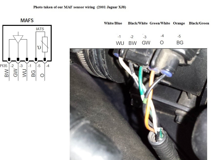
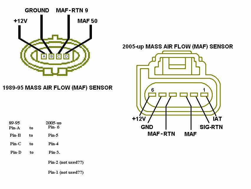
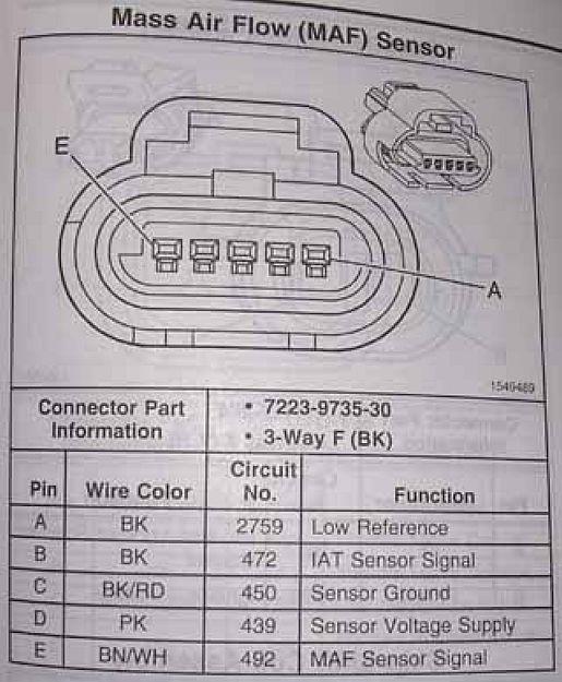
What two wires go to maf/iat sensor on a 5 wire plug
The mass air flow sensor or air flow sensor wiring diagram is designed by the manufacturer according to the year, model, construction, type, and demand. There are 4 forms of air flow sensor wiring diagrams. They are, 3-wire mass air flow sensor wiring diagram (hot wire-reference voltage from ECU, ground wire, signal wire).
4 Pin Maf Sensor Wiring Diagram Wiring Diagram Schemas
A 3 pin MAP sensor has three terminals: power, ground, and signal. The power wire provides the sensor with constant voltage, the ground wire connects the sensor to a ground source, and the signal wire sends the detected pressure reading to the ECM. 4 Pin MAP Sensor
3 Bar Map Sensor Wiring Camaro5 Chevy Camaro Forum / Camaro ZL1, SS
Among them, the 3-wire mass air flow sensor plays a crucial role in monitoring air intake. Delving into its wiring diagram unlocks a realm where precision meets performance, enabling enthusiasts to fine-tune their engine's potential. Let's shed light on this diagram, unraveling the secrets to harnessing the engine's untamed energy.
Mazda 2 Maf Sensor Wiring Diagram Robsten the true love
MAF MASS AIR FLOW SENSOR ELECTRICAL CONNECTIONS THEORY AND TROUBLESHOOTING FROM WIRING DIAGRAM Automotive electronics from schematics by Joseph 10.7K subscribers Subscribe Subscribed.

[DIAGRAM] 1 8t Iat Sensor Wiring Diagram
A three-wire MAF sensor configuration consists of the following wires: Hot Power Wire: This wire serves as a reference voltage sourced from the ECU. It powers the MAF sensor. Ground Wire: Connected to the ECU, it provides grounding for the MAF sensor.
Fuse Box Toyota Camry 1993
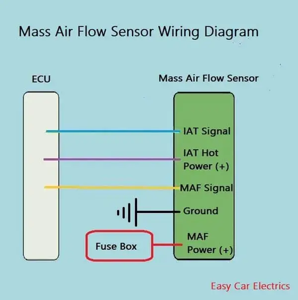
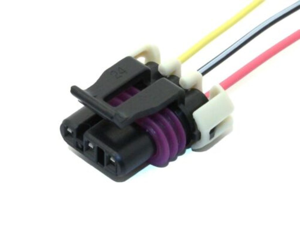
In this example, the red wire provides power to the MAF sensor, the black wire is the ground connection, the blue wire carries the voltage signal from the sensor, and the green wire measures the intake air temperature.. Importance of the Mass Air Flow Sensor Wiring Harness. The MAF sensor wiring harness plays a crucial role in the proper functioning of the MAF sensor and overall engine.

MAF IAT Sensor Wiring Diagram
By learning how to interpret the 3 pin mass air flow sensor wiring diagram, you'll be able to identify any potential wiring problems and ensure accurate sensor readings.. It is important to properly wire a 3 pin MAF sensor to ensure its functionality. Incorrect wiring can result in inaccurate airflow measurements and potentially cause.
02 5.3l Maf Wiring Diagram Handicraftsism
How to test a MAF Sensor using a basic multimeter without having to look up a wiring diagram. If you liked this video you may find these other videos useful.

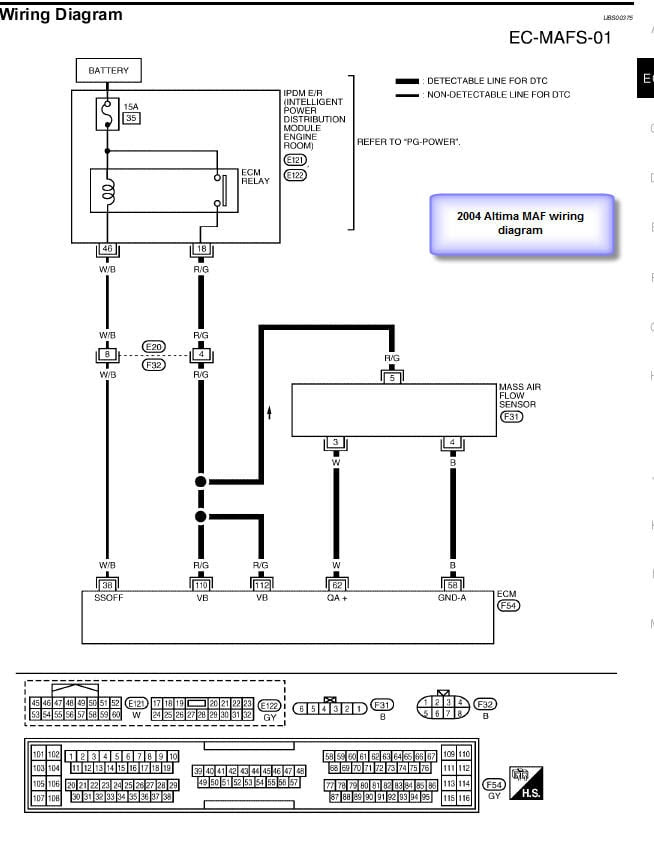
I need a mass air flow sensor wiring diagram to a 2013 ford explorer
A three-wire sensor has 3 wires present: two power wires and one load wire. The power wires will connect to a power supply and the remaining wire to some type of load. The load is a device that is being controlled by the sensor. The most common type of load would be a PLC (programmable logic controller) DC input.

Repair Guides
A 3 wire MAF sensor measures the amount of air flow entering the engine. The first wire measures the voltage coming from the mass air flow (MAF) sensor. The second wire is the ground wire, and the third wire is the signal wire that goes to the engine control unit (ECU).

Bmw E46 Maf Wiring Diagram
The MAF sensor must be oriented correctly in the induction system - cover. note the arrow on the sensor indicating flow direction. Be sure to weld the mounting boss correctly - engines air cleaner system and must be between the MAF the sensor will only mount one way in the boss (see diagram). and engine's throttle body. The engine burns.

Bmw E46 Maf Wiring Diagram
MAF Sensor & Wiring DiagramsAmazon Printed Bookshttps://www.createspace.com/3623928Amazon Kindle Editionhttp://www.amazon.com/Automotive-Electronic-Diagnosti.
3 Wire Maf Sensor Wiring Diagram DiagramInfo
I am hooking up an EFIE between my MAF sensor and my ECU to help with my gas mileage in my HHO system. All the diagrams that came with the unit show a 3 wire sensor not a four wire as I have in my s70. Thanks, - Jesse. 1998 S70 T5 SE 290,000 KM sideswiped total loss (Sweet ride!) 2007 S60 2.5T loaded 63,000 KM SOLD!

Mass Air Flow Sensor Wiring Diagram Diagram Stream
Testing a 3 wire GM mass air flow sensor - before replacing it based on the P0102, test to confirm the wiring integrity is good (the power and ground, as well as the computer and signal.
4 Wire Maf Sensor Wiring Diagram Wiring Diagram Schemas
A three-wire MAF sensor consists of three wires, power, ground, and signal, which are listed below. Hot Power Wire (Reference voltage comes from the electronic control unit) Ground Wire Signal Wire (Gives Signals to the electronic control unit) The hot wire is a feed power source that is taken from the car computer (electronic control unit).
