Premium Vector Diode bridge rectifier component symbol for circuit
What Does the Diode Rectifier Symbol Do? Ratings of a Rectifier Diode Forward Biased Rectifier Diode Reverse Biased Diode What are the Popular Rectifier Diodes? How to Test a Rectifier Diode? Write the Purpose of a Rectifier Diode. What is the symbol of a rectifier diode? What are the types of rectifier diodes?

Free photo Diode Symbol Circuit Rectifier Electronic Max Pixel
A rectifier is an electrical device which is used to convert AC current into DC current. Rectifier does this process by allowing current (I) to flow through any device and the process taking place here is called rectification. Rectifier works by using diodes which are like one-way valves for electricity.

Símbolos de Puentes Rectificadores Basic electronic circuits, Diode
A rectifier diode is a type of electronic device that allows current to flow in only one direction. It is commonly used in power supplies and electronic circuits to convert alternating current (AC) into direct current (DC). The rectifier diode consists of a p-n junction, where the p-side is connected to the positive terminal and the n-side is.

diode bridge rectifier symbol electronic symbol with black color
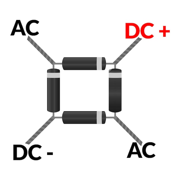
A three phase rectifier converts the three phase electrical signal into a DC rectified output. it is a modified form a full wave bridge rectifier where 2 pair of diodes converts each phase. Related Electronic and Electrical Symbols: Basic Electrical and Electronic Symbols; Transformer Symbols; Motors Symbols; Generator and Alternator Symbols
diode bridge rectifier symbol electronic symbol with black color
A rectifier is an electronic device that converts an alternating current into a direct current by using one or more P-N junction diodes. A diode behaves as a one-way valve that allows current to flow in a single direction. This process is known as rectification.
International Rectifier Logo PNG Transparent & SVG Vector Freebie Supply
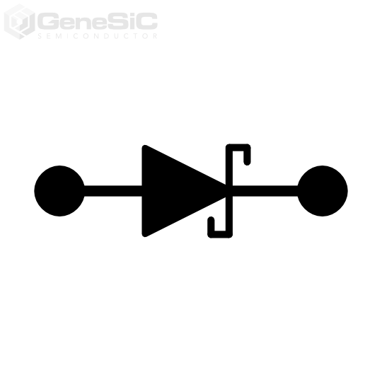
A symbol for rectifier diode is a line with an arrow, showing current flow from anode to cathode, commonly used in circuits.

Circuit Diagram Of Diode
The basic schematic symbol for a diode looks like an arrow head that points in the direction of conventional current flow from its Anode (A) terminal to its Cathode (K) terminal. The schematic symbol of a diode also shows that if forward-biased, current will flow through the direction of the arrow.
Symbol Triangle Rectifier Transparent PNG
Symbol of Rectifier diode Rectifier diode symbol Since a Rectifier diode is a PN junction diode, its symbol is a triangle pointing to a straight line. The triangle shows the direction in which the diode allows the current flow i.e, towards the straight line.
rectifier symbol Cheaper Than Retail Price> Buy Clothing, Accessories
Rectifier AC to DC Power Converter Symbols. Electrical symbols of AC/AC, DC/DC converters, AC/DC rectifiers and DC/AC inverters
Rectifier clipart 20 free Cliparts Download images on Clipground 2023
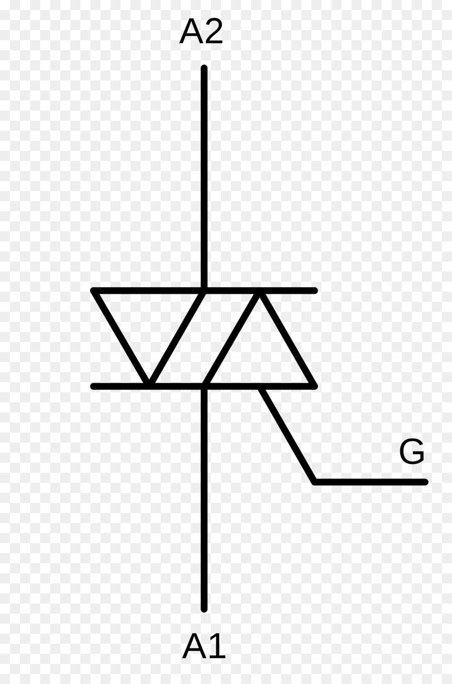
The Silicon Controlled Rectifier (SCR) is the most important and mostly used member of the thyristor family. SCR can be used for different applications like rectification, regulation of power and inversion, etc. Like a diode, SCR is a unidirectional device that allows the current in one direction and opposes in another direction.
ترياك, الإلكترونية رمز, Silicon Controlled Rectifier صورة بابوا نيو غينيا
A rectifier is an electrical device that converts alternating current (AC), which periodically reverses direction, to direct current (DC), which flows in only one direction. The reverse operation (converting DC to AC) is performed by an inverter . The process is known as rectification, since it "straightens" the direction of current.
Master Symbol Register
A silicon controlled rectifier or semiconductor controlled rectifier is a four-layer solid-state current -controlling device. The name "silicon controlled rectifier" is General Electric 's trade name for a type of thyristor.

Schematic Symbol Of An Ideal Diode ClipArt Best
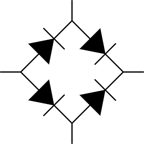
The full wave rectifier circuit consists of two power diodes connected to a single load resistance (R L) with each diode taking it in turn to supply current to the load.When point A of the transformer is positive with respect to point C, diode D 1 conducts in the forward direction as indicated by the arrows.. When point B is positive (in the negative half of the cycle) with respect to point C.

What is Silicon Controlled Rectifier SCR » Electronic devices » Hackatronic
Rectifier symbols for use in electrical, pneumatic and hydraulic schematic diagrams. Available in SVG, PNG, JPG, DXF & DWG formats

Silicon Controlled Rectifier Scr Electrical Theorems Silicon
Rectifier Diode Symbol Rectifier Diode Circuit Working. Both the n-type & p-type materials are chemically combined with a special fabrication technique which results in the formation of a p-n junction. This P-N junction has two terminals which can be called as electrodes and due to this reason, it is called to be a "DIODE "(Di-ode)..
Electrical Symbols — Composite Assemblies Composite assemblies
Simply defined, rectification is the conversion of alternating current (AC) to direct current (DC). This involves a device that only allows one-way flow of electric charge. As we have seen, this is exactly what a semiconductor diode does. The simplest kind of rectifier circuit is the half-wave rectifier.
